|
BE
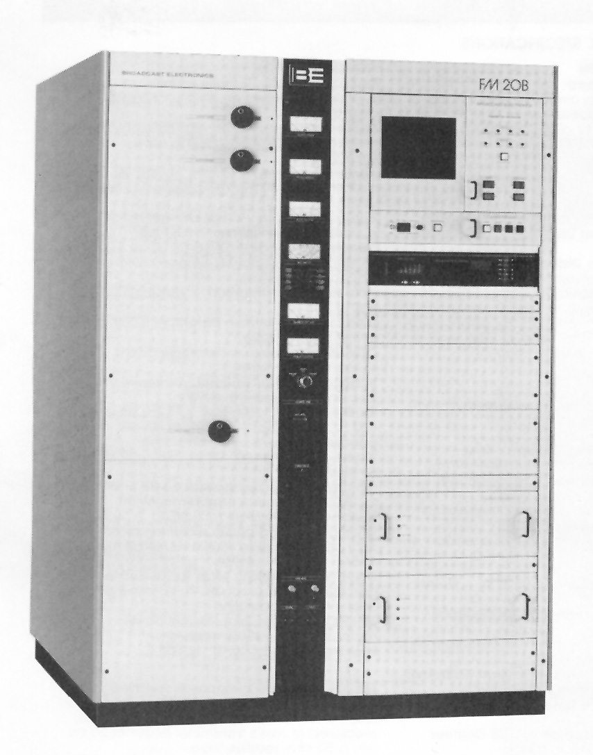
FM-20B, 20 KW FM Transmitter
GENERAL
SPECIFICATIONS
Power
Output:
20 kW (7.5 kW to 22.0 kW)
PA Efficiency:
80% typical
Frequency
Range: 87.5 to 108 MHz, tuned to specific
operating frequency; exciter programmable In 10 kHz steps
RF Output
Impedance: 50 ohm (others on special
request)
Output
Connector: 3 1/8" EIA flange
VSWR:
1.8:1 maximum. (will operate into higher VSWR
with automatic power reduction) Frequency Stability: : +/-
300 Hz, 0° to 50° C
Type of
Modulation: Direct frequency modulation of
carrier frequency
Modulation
Capability: Greater than +/-350 kHz
Modulation Indication: Peak reading, color coded, LED display
with baseband overmodulation indicator
Exciter:
Solid state, 50 watt output, model FX50;
incorporating a digitally programmed synthesizer. (10 kHz
Increments)
Pre-Emphasis:
FCC 75 uS, CCIR 50 uS (where specified),
25 uS (Dolby), or fiat response, selectable
Asynchronous AM
SIN Ratio: 55 dB below reference carrier with 100% amplitude
modulation at 400 Hz, 75 uS de-emphasis (no FM modulation present)
Synchronous AM
SIN Ratio: 50 dB below 20 kW reference
carrier with 100% AM modulation at
1 kHz, no
de-emphasis (FM modulation +/-75 kHz at 1 kHz)
Tube
Complement: 8989/4CX12000A
RF Harmonics:
Suppression meets all FCC/DOC requirements
and CCIR recommendations
Power Supply
Rectifiers:
Silicon
ELECTRICAL/MECHANICAL
AC Input Power:
208/240 VAC, Delta or WYE,
60 Hz, three phase
(taps for 196 to 252 VAC; other voltages and line frequencies
available upon request)
Primary Power
Consumption: 30.0 kW (at 0.97 pf) at 20 kW
RF output
Overall
Efficiency: Typically 67% (AC line Input
to RF output)
Size:
(Transmitter) 50S' W x 31.5" D x 70" H (128.3 W x
80 D x 177.8 cm)
(Power Supply)
28.5" W x 31.5" D x 70" H
(72.4 W x 80 D x
177.8 H cm)
Weight
&
Cubage:
(Transmitter) 1200
Ibs
(545 kg); 75 cu.
ft. (2.1 cu. meters);
(HV Power Supply)
1500 Ibs (681
kg);
45 cu. ft. (1.3 cu. meters)
Altitude:
10,000 ft at 60 Hz (3048 M), 7500 ft at 50
Hz (2286 M)
Ambient
Temperature Range: -10° to +50° C
TECHNICAL
SPECIFICATIONS
MONAURAL OPERATION
Audio Input
Impedance: 600 ohm balanced, resistive,
adaptable to other impedances, 60 dB common mode suppression
Audio Input
Level: + 10 dBm nominal for
+/-75 kHz
deviation at 400 Hz
Audio Frequency
Response: :to.5 dB, 30 Hz to 15 kHz,
selectable flat; 25, 50, 75 uS pre-emphasis
Total Harmonic
Distortion + Noise:
0.02% or less at
400 Hz
SMPTE
Intermodulation Distortion:
0,02% or less, 60
Hz/7 kHz 4:1 ratio
CCIF
Intermodulation Distortion:
0.02% or
less,
15 kHz/14 kHz 1:1 ratio
Transient
Intermodulation Distortion:
0,02% or
less, sine
wave/square wave
FM
SIN Ratio: 85 dB below +/-75 kHz deviation at
400 Hz, measured in a 20 Hz to 30 kHz bandwidth with 75 uS
de-emphasis
WIDEBAND COMPOSITE
OPERATION
Composite
Inputs: 3 total, (1) unbalanced and (1)
balanced plus front panel test; all
connectors BNC
Balanced Composite
Input Impedance:
10K or 50 ohm,
nominal, resistive, selectable Unbalanced
Composite Input Impedance:
10K ohm, nominal,
resistive
Composite Input
Level: 3.5 V pop nominal, for
+/-75 kHz
deviation
FM
SIN Ratio: 85 dB below +/-75 kHz deviation at
400 Hz, measured In a 20 Hz to 30 kHz bandwidth with 75 uS
de-emphasis
Composite Total
Harmonic Distortion + Noise:
0,02% or less at
400 Hz
Composite SMPTE
Intermodulation Distortion:
0.02% or
less,
60 Hz/7 kHz 1:1 ratio
Composite CCIF
Intermodulation Distortion:
0.02% or
less,
15 kHz/14 kHz 1:1 ratio
Composite
Transient Intermodulation Distortion:
0.02% or
less,
sine wave/square wave
Composite Amplitude Response: :to.05 dB,
30 Hz to 53 kHz
Composite Phase
Response: :to.25 degrees from linear
phase, 30 Hz to 53 kHz
Composite Group
Delay: 125 nanoseconds Composite Slew
Rate: 9 V/microsecond (symmetrical)
Subcarrier
Inputs: (3) total, unbalanced, BNC
connectors
Subcarrler
Input Impedance: 1O0K ohm, nominal,
resistive
Subcarrier
Input Level: 3,5 V pop, nominal, for
+/-7 ,5 kHz
deviation
Subcarrier
Amplitude Response: :to.2 dB,
40 to 100 kHz
STEREO OPERATION
Modulation
Type: Digitally synthesized stereo,
digitally synthesized pilot; no pilot phase adjustment required
Audio Input
Impedance: 600 ohm balanced, resistive,
floating (adaptable to other impedances)
Audio Input
Level: +10 dBm, :t1 dB, for 100%
modulation at 400 Hz (adaptable to other input levels)
Audio Input
Filters: 15 kHz LPF with delay
equalization for minimum overshoot
Frequency
Response: :to.5 dB, 30 to 15,000 Hz, 75 uS
pre-emphasis (flat, 25 or 50 uS preemphasis selectable)
Total Harmonic
Distortion + Noise:
0.05% or less at
400 Hz
SMPTE
Intermodulation Distortion:
0.05% or less, 60
Hz/7 kHz 4:1' ratio
CCIF
Intermodulation Distortion:
0.05% or less, 15
kHz/14kHz 1:1 ratio
Transient
Intermodulation Distortion:
0.05% or less,
sine wave/square wave
FM SIN Ratio:
82 dB below +/-75 kHz deviation at 400 Hz,
measured in a 20 Hz to 30 kHz bandwidth with 75 uS de-emphasis
Stereo
Separation: 50 dB or better; 30 to 15,000
Hz (sine wave)
Dynamic Stereo
Separation: 50 dB or better; 30 to 15,000
Hz (normal program content)
Linear
Crosstalk: Main to Sub/Sub to Main due to
amplitude and phase matching of left and right channels, 30 to
15,000 Hz, 45 dB minimum below 100% modulation
Non-Linear
Crosstalk: Main to Sub/Sub to Main due to
distortion products. 70 dB minimum below 100% modulation
38 kHz Subcarrler
Suppression:
80 dB, minimum, below 100% modulation
Pilot
Stability: +/- 0.5 Hz, 0° to 50° C
FM
20B system performance is specified using model FX 50 FM Exciter, FS
30 Stereo Generator, and FC 30 SCA Generator where applicable,
measured at rated transmitter power of 20 kW into a 50 ohm resistive
load.
|